Main window
The main window of send2cnc is the central working area of the application, providing all important functions and tools. It includes the render window for displaying 3D objects and scenes, the menu bar for accessing main functions, project tabs for open projects, the project tree for organizing objects and layers, and the object info box, which displays information about selected objects.
 © send2cnc.com
Main menu
The main window has a menu at the top that allows access to the various program functions and settings. It is divided into logically structured sections. Each category in the menu has a title and the most important functions as icons for quick access. Clicking on the category name opens a pop-up menu containing all the functions in that category.
 © send2cnc.com
Menu category "File"
This menu group contains the file management for input and output, as well as the general control of the program.
New
Creates a new project and starts with an empty workspace.
Open
Opens an existing project or template.
Save
Saves the current state of the open project or template.
Save as
Saves the currently open project or template under a new file name.
Save as template
Saves the currently open project as a template under a new file name. The template folder is automatically selected.
Close project
Closes the currently open project.
Quit
Asks whether the open projects should be saved and then exits send2cnc.
Menu category "Edit"
This menu group contains general functions for selected objects.
Cut
Removes the selected objects from the project tree and copies them to the clipboard.
Duplicate
Creates a copy of the selected objects.
Copy
Copies the selected objects to the clipboard. Subordinate objects are not copied unless they are also selected.
Paste
Inserts the objects from the clipboard into the project.
Remove
Removes the selected objects from the project.
Remove all references
Deletes all links between the selected objects and other objects. This is useful when objects are inserted from another project.
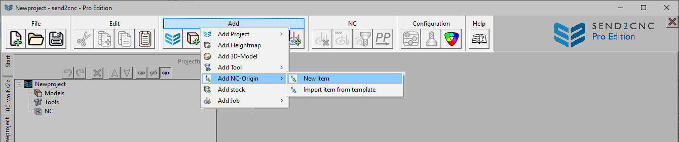
Menu category "Add"
This menu group contains functions for adding or importing new objects.
Create project
Creates an empty project or generates a project based on a template.
Create heightmap
Creates an empty heightmap object. Various options for generating the geometry are available in the configuration dialog, which opens automatically after creation.
Create 3D model
Creates an empty 3D model object. Various options for creating the geometry are available in the configuration dialog, which opens automatically after creation.
Create tool
Creates an empty tool object or loads one from a template. The geometry is defined with the tool editor, which opens automatically after an empty tool has been created.
Create workpiece origin (NC-Zero)
Create or load a workpiece origin with the job objects contained in a template. A workpiece origin defines the origin for the contained jobs. The location and orientation can be set in the Configuration dialog box.
Create blank
Creates an empty blank object. Various options for generating the geometry are available in the configuration dialog, which opens automatically after creation.
Create job
Creates an empty job object or loads one from a template. Includes all parameters for calculating a toolpath. The parameters can be defined in the configuration dialog, which opens automatically after creation.
Menu category "NC"
The NC menu group contains functions for managing toolpaths.
Reset toolpath
Deletes the calculated toolpath. The Job Object itself remains intact.
Calculate toolpath
Deletes the existing toolpath if necessary and calculates the job object. If successful, a toolpath is generated.
Solid Live Simulation
Starts the "send2cnc - Solid Live Simulation" environment. This allows the selected toolpaths to be simulated.
Postprocessor
Starts the postprocessor environment to translate the calculated jobs into executable NC programmes.
Menu category "Configure"
This menu group contains functions for configuring the system and selected objects.
Configure object
Opens the corresponding configuration dialog for the selected object, depending on the object type.
Tool editor
Opens the tool editor for the selected tool to edit or define the geometry.
Color Library
Opens the color library to create and modify colors.
License Manager
Opens a dialog window for managing the license in use. The License Manager displays the current license status and can be used to load or remove a license.
System settings
This dialog window allows you to customize the program.
A detailed description of all the settings can be found in the chapter "Settings".
Help menu
The help menu contains functions for displaying documentation and information about send2cnc.
Open user manual
Opens the table of contents of the user manual. You can choose between the online version and the local version.
Program files
Opens the folder in Explorer in which send2cnc stores temporary data, settings files, templates, example projects and postprocessors.
Update
Opens the send2cnc information dialog, which includes a link to check for available updates.
About send2cnc
Displays basic information about send2cnc.
Project tabs
In the main window, vertically arranged tabs for each open project can be found on the left side. Clicking on one of these tabs changes the active project.
 © send2cnc.com
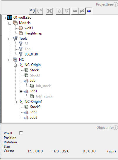
Project tree
The project tree is a central element in the send2cnc workflow and shows the structure of the entire project. The context menu opens by right-clicking on one or more selected objects, dynamically adapts to the selection and offers almost all the functions of the main menu.
Object types and structure
This section provides an overview of the object types and the tree structure of a project.
The project tree is hierarchical and has a fixed structure. The top-level object is the project element and has the same name as the saved project file. The project element contains all other objects.
Fixed folders
Every project has fixed folders from the outset:
| Folder | Description |
|---|---|
| Models | Contains all heightmaps and models of the project |
| Tools | Contains all tools of the project |
| NC | Contains all workpiece origins of the project |
Creatable Objects
The following table lists all the objects that can be created:
| Object | Parent element | Short description |
|---|---|---|
| Heightmap | Models | A 3D geometry generated from 2D data. |
| 3D model | Models | A 3D geometry consisting of facets. |
| Tool | Tools | Contains the cutting and shank geometry of an NC tool, as well as tool-relevant parameters. |
| Workpiece origin | NC | Determines the workpiece origin for the containing jobs |
| Blank | Workpiece origin | A heightmap that specifies the geometry of the starting material (blank) for the calculation. |
| Job | Workpiece point | A job object contains all references and parameters for the toolpath calculation. |
Calculated Objects
The following table lists all automatically calculated objects:
| Object | Parent element | Short description |
|---|---|---|
| resulting blank | Job | Is calculated from the tool and blank reference of the job and the tool path. Can be used as a reference for following jobs. |
| collision evaluation | Job | This optional object is created when a collision is detected during the calculation of the toolpath. It indicates the points of collision. |
Text color
The text color of the elements in the project tree provides information about the state and properties.
| Text color | Meaning |
|---|---|
| blue | The object is referenced by a selected object. |
| red | The object references a selected object. |
| pale color | The object is hidden. |
References
References are links between objects in the project. An object can read the data and properties of the reference, but not change them. To prevent reference loops, some reference types only allow references that are located above the object in the hierarchy.
Special references are described in the general chapter for reference lists
Object name
The object name must be unique within the project. If the name already exists, a sequential number is added to the name.
Project tree functions
Undo
Reverses the last change made to the hierarchy.
Redo
Reinstates the previous change to the hierarchy.
Delete
Deletes the selected objects from the project.
Up
Moves the selected object up in the hierarchy.
Down
Moves the selected object down in the hierarchy.
Show
Shows the selected objects. To ensure that the object is actually shown in the render window, you must also make sure that the corresponding layer is shown in the render window toolbar. Use the <> key to toggle the visibility of an object.
Hide
Hides the selected objects. An object remains hidden even if the corresponding layer of the object type is shown in the render window toolbar. Use the <> key to toggle the visibility of an object.
Automatically show/hide jobs
When this mode is activated, selected jobs are automatically shown. Jobs that are not selected are automatically hidden.
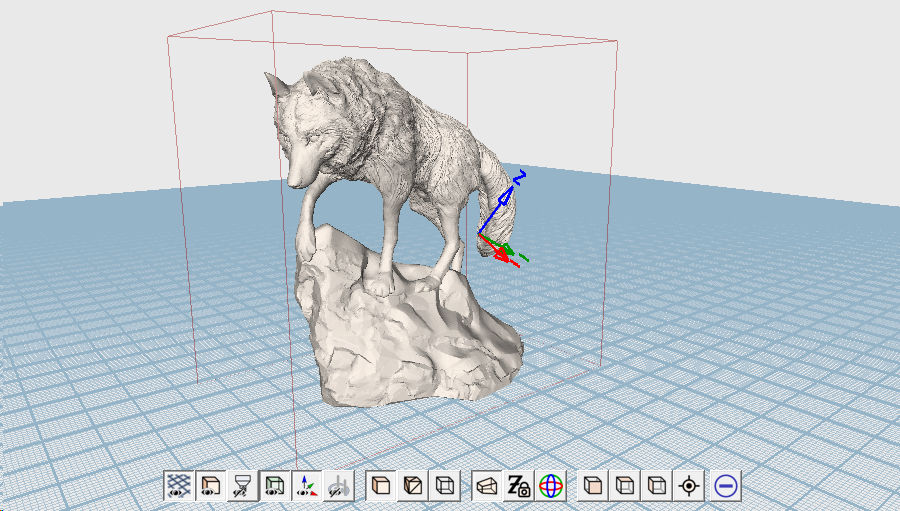
Render window
The render window is the central visualization element in send2cnc. It shows the 3D view of the objects contained in the project tree and allows interaction and navigation in the scene.
 © send2cnc.com
Workplane
 © send2cnc.com
Absolute zero
Absolute zero is shown as a gray coordinate system and is the origin of the project scene. It determines the three main axes X, Y and Z. The camera control and the work grid are based on this zero point.
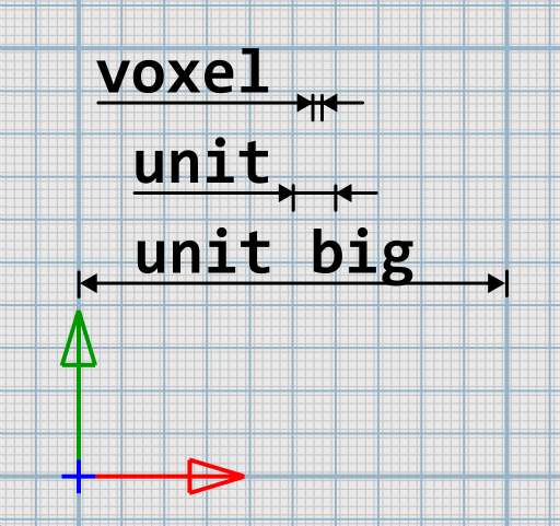
Work grid
The work grid in the Render view is located on the Z-plane of absolute zero. The extent of the work grid can be used as a guideline for the maximum size of the models. It adapts dynamically to the project resolution and consists of the following scales:
| Grid | Display | Scale | Remark |
|---|---|---|---|
| Voxel | Fine lines | 1 voxel | Shifted by half a voxel to absolute zero. |
| Unit | standard lines | 1 user unit | Represents the distance of 1 voxel x project resolution |
| Unit big | bold lines | 10 user units | Represents 10 times the distance of a unit. The factor can be changed in the settings. |
Toolbar
The toolbar is located at the bottom of the render window and offers functions for controlling the display and the camera. On the far right of the toolbar, there is a blue plus sign in a circle. When the plus is activated, the toolbar expands to include some additional functions. All functions are listed below, with the extra functions marked with a (+).
Group Layer
The "Layer" group of symbols controls the visibility of individual object groups. Regardless of the layer status, objects always remain hidden if they are hidden in the project tree (see also Project Tree Functions).
| Layer | Description |
|---|---|
| Workplane | Shows/hides the workplane grid |
| Model | Shows/hides heightmaps and 3D models |
| Tool | Shows/hides tools |
| Blank | Shows/hides blanks |
| (+) Workpiece Zero | Shows / hides the coordinate systems of the workpiece zero objects |
| Job | Shows/hides jobs and the toolpaths they contain |
Group View
Controls the general display mode of the objects.
| Display | Description |
|---|---|
| Solid | Shows the objects as solid surfaces |
| Solid+wireframe | Displays objects as solid surfaces with visible wireframe overlays |
| Wireframe | Shows the objects in wireframe mode |
Camera group
Controls the behavior of the camera and the projection mode. The keyboard shortcuts for camera control are described in the chapter Shortcuts
| Function | Description |
|---|---|
| (+) Projection mode | Switches between perspective and orthogonal projection |
| (+) Z-Lock | Prevents the camera target point from being moved in the Z direction. "3D Rotation" is automatically disabled. |
| (+) 3D Rotation | The camera allows rotation around two axes. Activating 3D rotation mode extends camera control to allow rotation around all three axes. "Z-Lock" is automatically disabled. |
View group
Sets the camera to a specific orientation.
| View | Description |
|---|---|
| (+) Front | Shows the scene from the front. Right-click to show the scene from behind |
| Top | Shows the scene from above. Right-click to show the scene from below |
| (+) Right | Shows the right side of the scene. Right-click to show the left side of the scene. |
| Reset | Resets the camera to the original orientation. |
Advanced Features
Shows and hides additional functions in the toolbar.
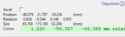
Object Info
The object info area displays information about selected objects, such as position, rotation, size and cursor coordinates.
 © send2cnc.com
Voxel unit
This switch can be used to change the unit of the values displayed in the object info box to "Voxel".
Position
The position information indicates the coordinates of the selected object relative to the global origin or, depending on the current selection, relative to the workpiece origin.
Rotation
The rotation information displays the quaternion rotation values of the selected object relative to the global origin or, depending on the current selection, relative to the NC origin.
Size
The size information reflects the local size of the selected object.
Cursor
The cursor coordinates indicate the 3D position of the mouse relative to the global origin or, depending on the current selection, relative to the NC origin in the render window
By default, the coordinates have a white background and show the values based on the global origin. However, if only one object is selected and that object is a workpiece origin or the object is located in a workpiece origin object, the coordinates are displayed based on the workpiece origin. In this case, the coordinates have a light green background.