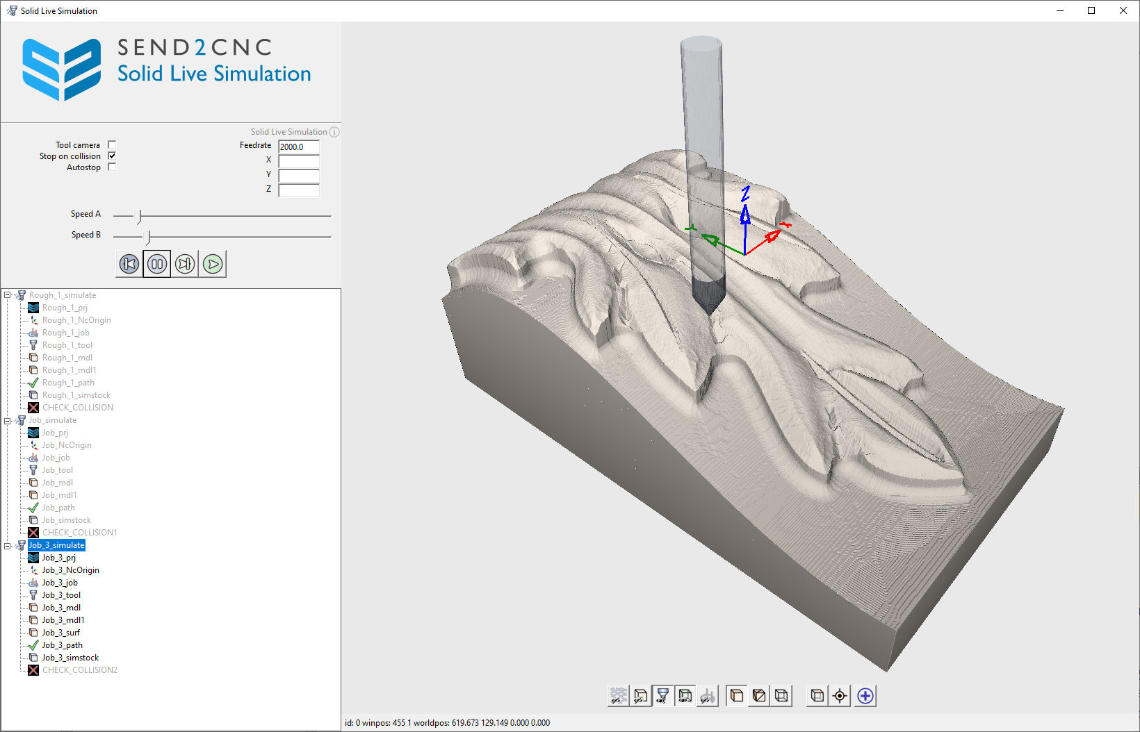
Solid Live Simulation <BASIC>
The calculated jobs can be visually checked using the virtual material removal simulation and analyzed for possible errors using the additional collision check.
 © send2cnc.com
A simulation can only be carried out if both a tool and a blank are available for the job to be simulated.
The Solid Live simulation environment supports starting with multiple jobs. In this case, the desired job to be simulated can be selected and activated in the tree structure. When the simulation environment is opened, the first simulation element is automatically activated.
It is possible to open more than one simulation window. However, running more than one simulation at the same time is not recommended as it can lead to performance issues and instability.
Simulation - Collision Check
In case of a collision, highlighted points are generated at the point of contact and the object "CHECK_COLLISION" is displayed. At the end of the simulation, a warning message is displayed if a collision has been detected.
Simulation control
Tool Camera
When the check box is selected, the camera follows the tool. The camera can still be rotated during the simulation, but it can no longer be moved.
Stop on collision
When the check box is selected, the simulation automatically stops at the collision point and issues a warning message.
Autostop
If the checkbox is activated, the simulation stops after each milling path section.
Feed
Displays the current feed rate.
Position
Displays the current position of the tool relative to the NC origin.
Speed A
Controls the simulation speed for rapid traverse and plunge movements.
Speed B
Controls the simulation speed for the regular milling feed, except for plunge movements.
Reset
Resets the activated simulation to the start.
Pause
Pauses the simulation.
Single Step
Executes a single step. Useful for analyzing critical areas.
Start
Starts the simulation.
Simulation Tree
This tree structure lists all elements for the simulation.
The basic elements in the tree structure are the simulation elements. These include all objects required to run a simulation. They are independent of other simulation elements in the tree structure.
When a simulation element is activated, all associated objects are displayed and all other simulation elements are hidden. It is possible to manually show or hide each element (even from inactive simulation elements).
Simulation - Render View
The Render View displays the material removal simulation. The controls are identical to those of the Render View of the main window.