 © send2cnc.com
Heightmap model
A heightmap model is a special type of 3D model in which the geometry is defined by a two-dimensional graphic with additional height information.
Unlike conventional 3D models, the design of the object is based entirely on the surface, while the sides and base are derived from the surface and therefore have no independent geometry.
Geometry mode
A heightmap model can be created, loaded or generated using various methods.
The following section explains all available modes:
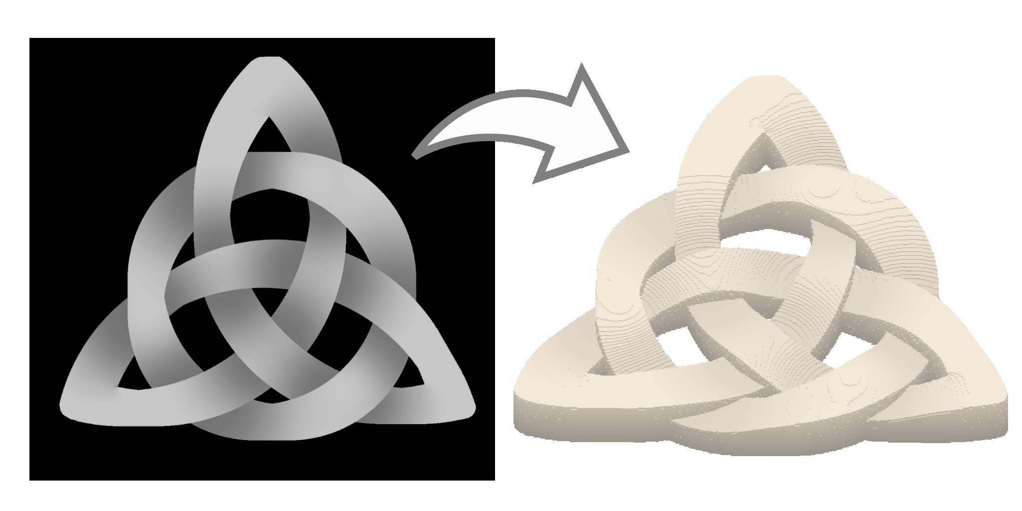
Image
The heightmap model is generated from an imported image, with the color value of each pixel determining the height. High color values create raised geometry. A color value of 0 creates a breach in the model. © send2cnc.com
The following tools and settings are available:
Import graphic
Opens the file manager to import a graphic.Reload Image
Reloads the already imported image from the stored file path and updates the heightmap model.
Import from Clipboard
Imports the graphic from the clipboard to generate the heightmap model.
Unlink file
This function removes the linked file path from the object, but retains the data of the last loaded file.
Color channel filter
Allows you to use certain color channels of the graphic.- rbg: Calculates the average brightness value of all color channels.
- Red: Uses only the red color channel to determine the height.
- Green: Uses only the green color channel to determine the height.
- Blue: Uses only the blue color channel for determining the height.
- Alpha: Uses the alpha channel for determining the height.
Inver Colors
Inverts the brightness values of the individual color channels.Shape
Creates a heightmap model based on a geometric base shape and user-defined dimensions.
 © send2cnc.com
Basic geometric shapes
- Block: rectangular block
- Cylinder: cylinder oriented along the z-axis
Dimensions
- x: model size in X direction
- y: model size in y-direction
- z: model size in z-direction
- Frame thickness [optional]: The specified dimension determines the frame thickness of the model. If no dimension is specified (0.0), the model is created as a solid shape.
Reshape
The heightmap model is formed from one or more existing models.
 © send2cnc.com
Shape
Determines the resulting form.
- Heightmap The height information for the heightmap is calculated based on the geometry references and the selected orientation reference.
- Box The referenced geometry is enclosed in a rectangular box aligned with the orientation reference – useful for creating a blank.
Geometry reference
One or more models can be selected that are merged into a single heightmap.
Orientation
The orientation of the resulting heightmap is aligned with the selected reference. The height axis of the heightmap corresponds to the z-axis of the selected reference.
Special references
Special references can also be used and are described in the general chapter for reference lists
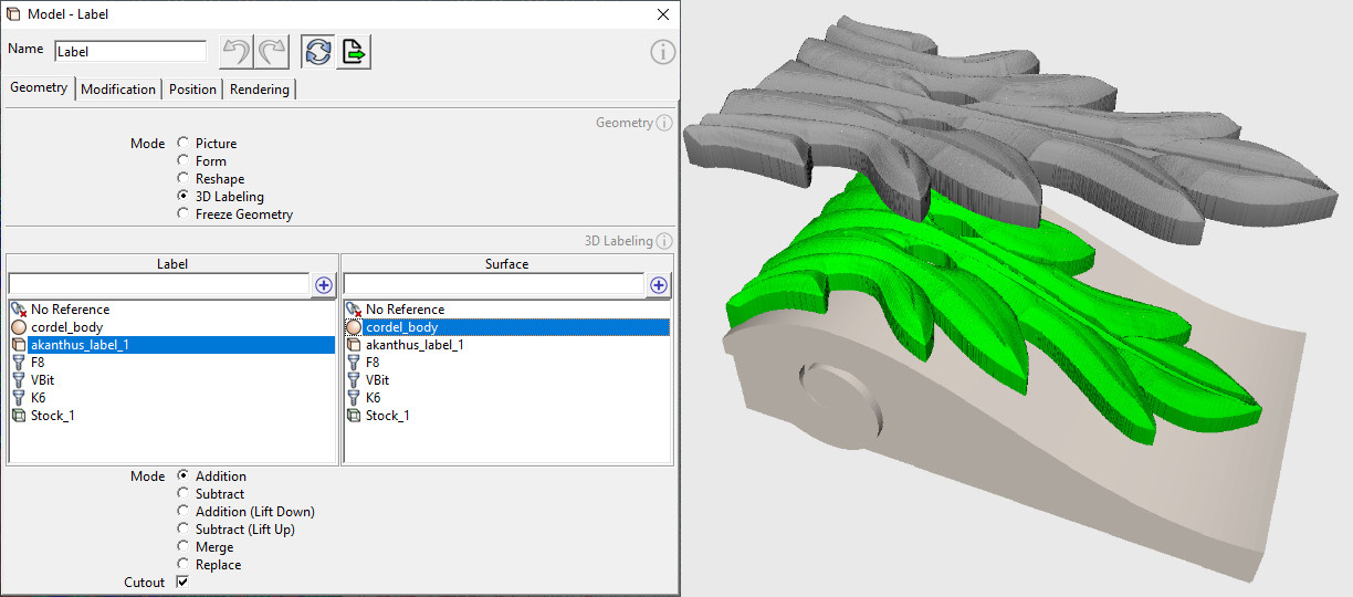
3D Labeling
Projects a model (sticker) onto the surface of another model.
This powerful feature can be used, for example, to display lettering, logos and even 3D models like an ornament on a 3D surface.
 © send2cnc.com
Label
Determines the model to be projected. Both heightmaps and native 3D models can be selected.
Surface
Determines the surface onto which the label is projected. Both heightmaps and native 3D models can be selected.
Projection mode
Determines how the label is projected onto the surface.| Mode | Description |
|---|---|
| Addition | [Default mode] The label is applied to the surface. |
| Subtract | The label is cut out from the surface |
| Addition (Z fixed) | The label is added to the surface and the resulting model is lowered by the thickness of the label. |
| Subtract (Z fixed) | The label is cut out of the surface and the resulting model is raised by the thickness of the label. |
| Merge | Both models are merged together (the Z position of the label plays a role in this). |
| Replace | The Z-value of the label replaces the Z-value of the surface. |
Cutout
The resulting model is limited to the area of the sticker.Special references
Special references can also be used and are described in the general chapter for reference lists
Freeze Geometry
Detaches the model from its geometry and position references.
Activating the "Freeze Geometry" mode freezes the geometry and position of the model. The dependency on geometry and position references is removed, making the model independent and allowing it to be freely positioned.
Heightmap Modifications
The modifications change the underlying 2D data set of the heightmap, from which the 3D geometry is generated.
 © send2cnc.com
The modifications are applied after the 2D data set has been read in and before the model is positioned and rotated using the settings in the "Position" tab. The parameters for the modifications are also retained when the 2D base data set is updated (e.g. by reloading a graphic).
A common modification that is often applied is scaling a model in the direction of the z-axis to determine the height of the heightmap.
Presets
The presets can be used to set or reset standardized modification values.
Reset Mods
Resets the modifications to the default values.
Mold (Inverted geometry and Position)
Inverts the geometry and position of the model to create a negative impression of the model.
This preset is also suitable for creating inlays.
An example is shown in the "Reshaping" section above.
Modifications
Invert height map
Reverses the height of the heightmap.
Invert Z position
Inverts the Z position so that the height map is upside down.
Lock Aspect Ratio
Locks the scaling ratio for the X and Y axes to preserve the proportions of the model.
Scaling
Scales the heightmap to the desired size. The scaling mode can be toggled between "Scaling factor" and "Absolute scaling" using the checkbox.
Mirror
Mirrors the geometry along the specified axis.
Allowance
An allowance can be defined individually for each (local) axis direction. Positive values expand the geometry in the respective direction, while negative values shrink it. The position of the model in 3D space is automatically corrected.
Cropping
Cuts the model by the specified values of the respective axis. The position of the model in 3D space is automatically corrected.